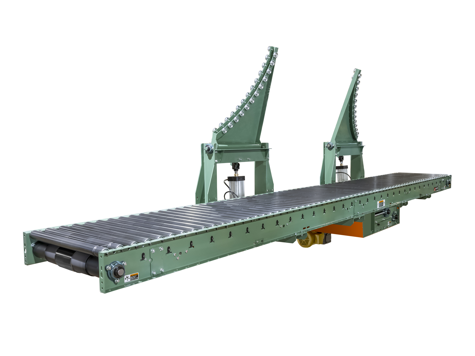
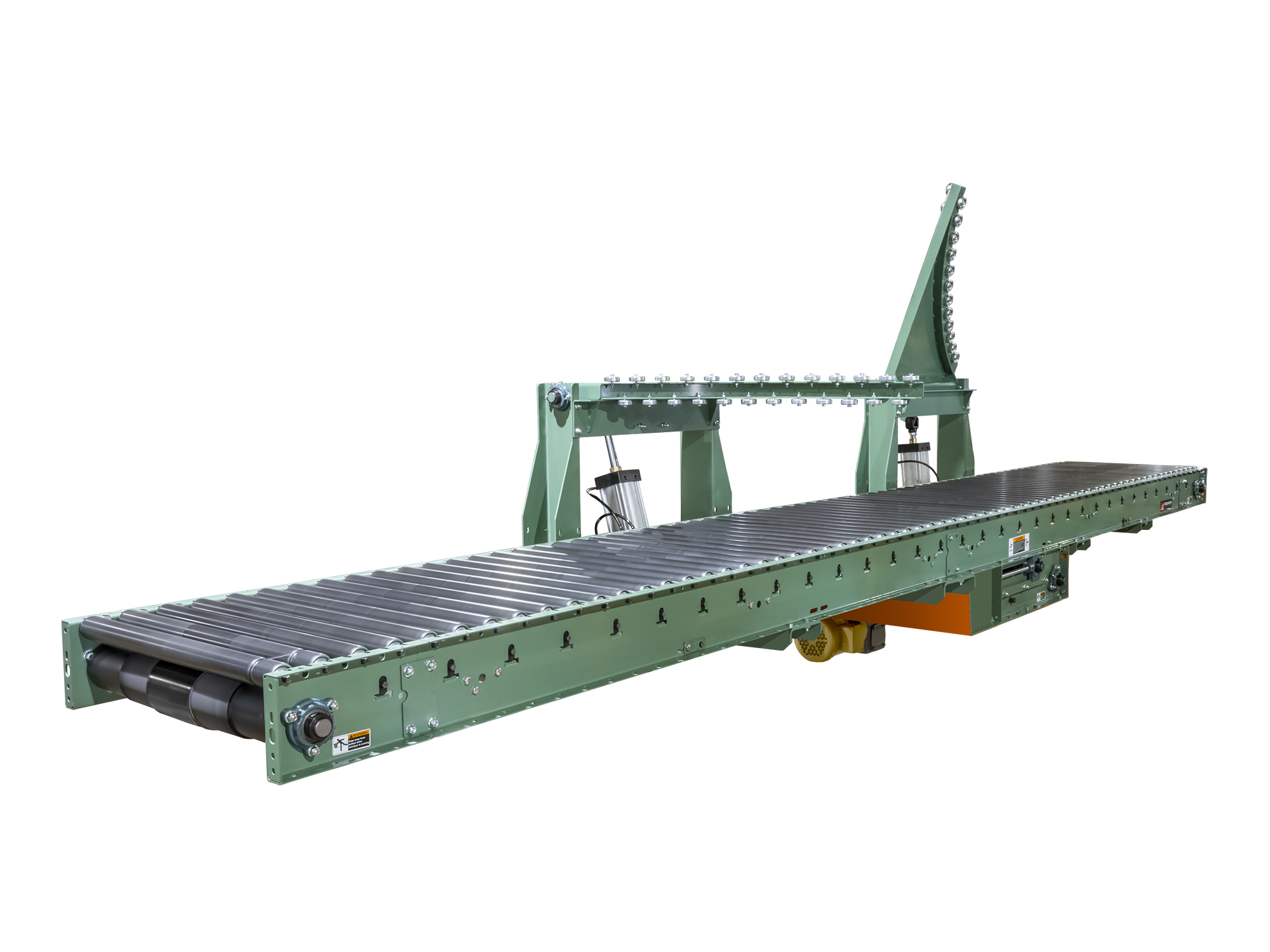
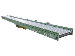
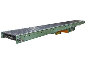
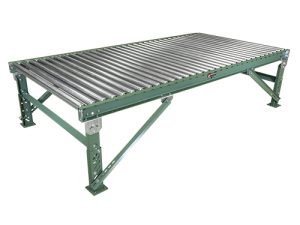
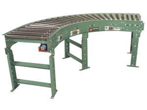
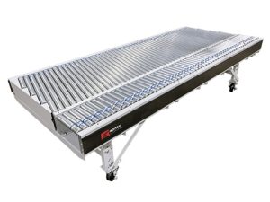
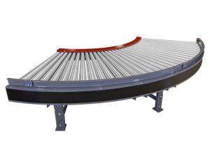
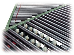
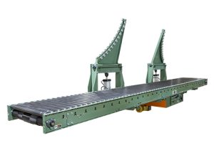
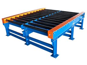
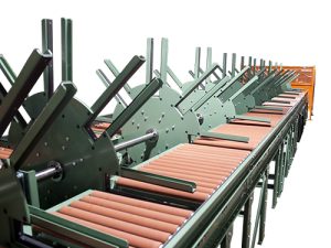
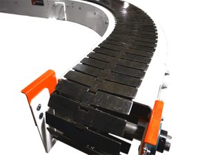
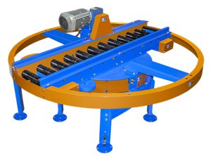
TREAD ROLLERS: 1-.9″ dia. x 16 ga. steel rollers, model 196S.
PRESSURE ROLLERS: 1.9″ dia. x 16 ga. steel, model 196S, cam adjustable.
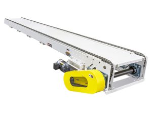
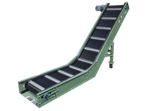
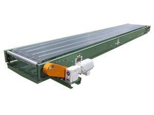
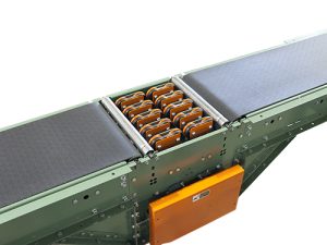
BELTING: 6″ wide black PVC-120 COS.
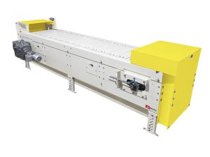
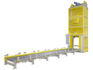
CENTER DRIVE: Reversible drive with 24″ integral belt take-up. For units under 8′-0″ overall length, drive components must be stacked. Consult factory for minimum unit elevation.
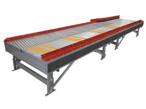
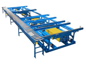
SQUARING RODS: Adjustable rods on underside of bed allow frame to be squared for improved belt tracking and are standard on all units over 30′.
DRIVE PULLEY: 4″ dia. with 1-3/16″ dia. shaft or 8″ dia. with 1-7/16″ dia. shaft; both crowned and fully lagged.
END PULLEY: 4″ dia., crowned, with 1-3/16″ dia. shaft.
RETURN ROLLERS: 1.9″ dia. x 16 ga. steel, model 196S
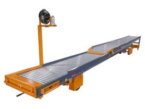
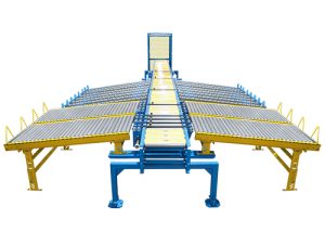
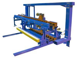
BED: 6″ x 1-1/2″ x 12 ga. channel frame slotted for tread rollers to pop-out. When unit is installed at 7′-0″ elevation or higher, rollers must be retained in conveyor frame. Specify desired elevation. Bed sections attached with couplings and floor supports.
FLOOR SUPPORTS: SM-6 adjustable 31-1/2″ to 43-1/2″ TOR. Supports should be lagged to floor.
BEARINGS: All pulley bearings are precision, heavy duty, lubricated, ball bearing units with cast iron housings.
ROLLER CHAIN: Drive pulley is driven by No. 50 roller chain for 1-1/2 HP or less and No. 60 chain on larger drives. Chain take-up provided on motor base.
MOTOR DRIVE: 1/3 HP, 230/460/3, 60 cycle, ODP right angle gear motor.
SPEED: 60 FPM, constant.
ELECTRICAL CONTROLS: Optional
|