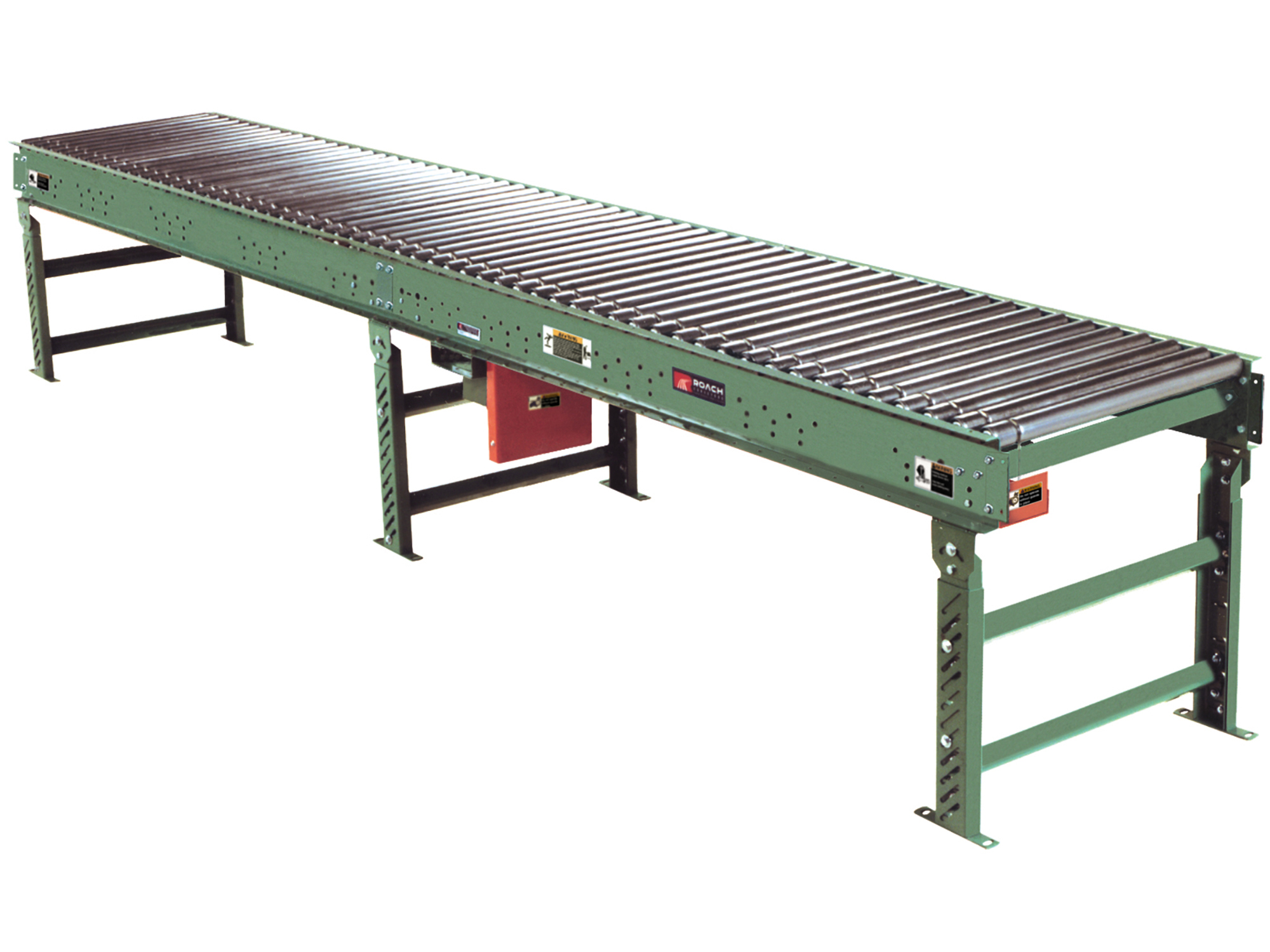
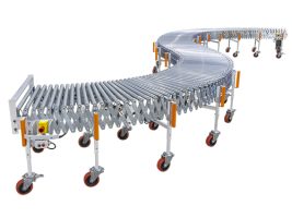
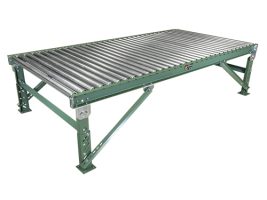
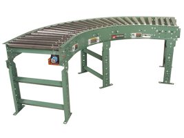
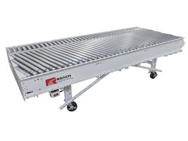
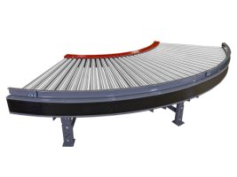
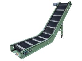
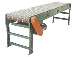
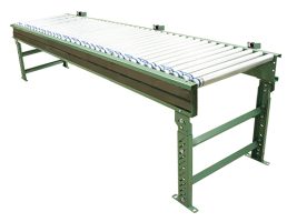
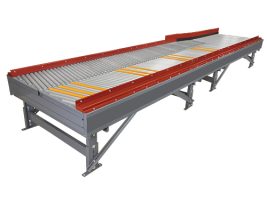
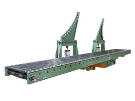
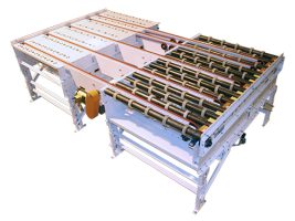
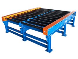
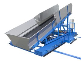
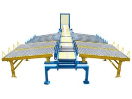
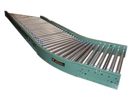
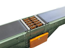
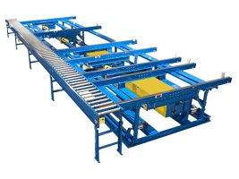
Model 796LSZ is one of the most popular accumulators in the unit handling industry. This zero pressure line shaft driven accumulator is ideal for numerous light to medium duty applications. Curves, spurs and other line shaft modules may be driven by a SINGLE drive.
796LSZ | Line Shaft Zero Pressure Accumulator Conveyor
| Specifications | TREAD ROLLERS: 1.9″ dia. x 16 ga. steel, model 196S grooved. DRIVE BELT: 3/16″ dia., polyurethane belts. Nominal 15 lbs. per roller drive. DRIVE SHAFT: 1″ dia. C1018 cold rolled steel shaft. COUPLINGS: Couplings located both ends (type “A”), one end only (type “B” or “C”) or none (type “D”). CENTER DRIVE: Located approximately 16-1/2″ from end of bed section on 4″ RC; 18″ on 3″ and 6″ RC. BEARINGS: All pulley bearings are precision, heavy duty, lubricated, ball bearing units with cast iron housings. ACCUMULATION: 2′-0″ zone length, pneumatically actuated, zone singulation operation. SPEED: 60 FPM, constant. BED: 7″ x 1-1/2″ x 12 ga. formed steel channel frame. Bed sections attached with splice plates and floor supports. FLOOR SUPPORTS: Optional FRL: Unit is provided with filter, regulator, lubricator with 1/4″ ports. PNEUMATIC ACTUATION: Maximum air line pressure should not exceed 30 PSI. MOTOR DRIVE: 1/3 HP, 230/460/3, 60 cycle, ODP right angle gear motor. ROLLER CHAIN: Drive shaft is driven by No. 50 chain. Chain take-up provided on motor base. ELECTRICAL CONTROLS: Optional |
|---|
796LSZ
Model 796LSZ is one of the most popular accumulators in the unit handling industry. This zero pressure line shaft driven accumulator is ideal for numerous light to medium duty applications. Curves, spurs and other line shaft modules may be driven by a SINGLE drive.
| Specifications | TREAD ROLLERS: 1.9″ dia. x 16 ga. steel, model 196S grooved. DRIVE BELT: 3/16″ dia., polyurethane belts. Nominal 15 lbs. per roller drive. DRIVE SHAFT: 1″ dia. C1018 cold rolled steel shaft. COUPLINGS: Couplings located both ends (type “A”), one end only (type “B” or “C”) or none (type “D”). CENTER DRIVE: Located approximately 16-1/2″ from end of bed section on 4″ RC; 18″ on 3″ and 6″ RC. BEARINGS: All pulley bearings are precision, heavy duty, lubricated, ball bearing units with cast iron housings. ACCUMULATION: 2′-0″ zone length, pneumatically actuated, zone singulation operation. SPEED: 60 FPM, constant. BED: 7″ x 1-1/2″ x 12 ga. formed steel channel frame. Bed sections attached with splice plates and floor supports. FLOOR SUPPORTS: Optional FRL: Unit is provided with filter, regulator, lubricator with 1/4″ ports. PNEUMATIC ACTUATION: Maximum air line pressure should not exceed 30 PSI. MOTOR DRIVE: 1/3 HP, 230/460/3, 60 cycle, ODP right angle gear motor. ROLLER CHAIN: Drive shaft is driven by No. 50 chain. Chain take-up provided on motor base. ELECTRICAL CONTROLS: Optional |
|---|
796LSZ
Accumulation Conveyors(9)
Accumulation
Belt Conveyors(10)
Belt Conveyors
Belt Driven Live Roller(7)
Belt Driven Live Roller
Chain Drag(5)
Chain Driven Live Roller(11)
Chain Driven Live Roller
Flexible Conveyors(2)
Flexible Conveyors
Gravity Conveyors(19)
Gravity Conveyors
Line Shaft(9)
Line Shaft
MCS | Modular Connect System(1)
MCS | Modular Connect System
MDZ | Motor Driven Zone Accumulator(2)
MDZ | Motor Driven Zone Accumulator
Parts Conveyor(3)
Parts Conveyor
Plastic Belt(9)
Plastic Belt
Powered Roller(13)
Powered Roller
Singulation(1)
Singulation
Slat Conveyors(2)
Slat Conveyors
Transfers(8)
Transfers
Wire Mesh Belt(4)
Wire Mesh Belt
Barrel Conveyors(3)
Barrel Conveyors
Glass & Solar Handling(8)
Glass & Solar Handling
Heavy Duty Conveyors(16)
Heavy Duty Conveyors
Laundry(11)
laundry
Lumber & Door(5)
Lumber
MDR | Motor Driven Roller Smart Conveyors(6)
MDR | Motor Driven Roller Smart Conveyors
Sortation Conveyors(7)
Sortation Conveyors
Special Transfers(11)
Special Transfers
Stackers | Destackers(2)
Stackers/Destackers
Stops | Barriers | Walkovers(10)
Stops | Barriers | Walkovers
Tabletop Chain Conveyors(5)
Tabletop Chain Conveyors
Transfer Carts(9)
Transfer Carts
Turntables(17)
Turntables
Vertical Conveyors(8)
Vertical Conveyors
Wheel & Tire Conveyors(4)
Wheel & Tire Conveyors

