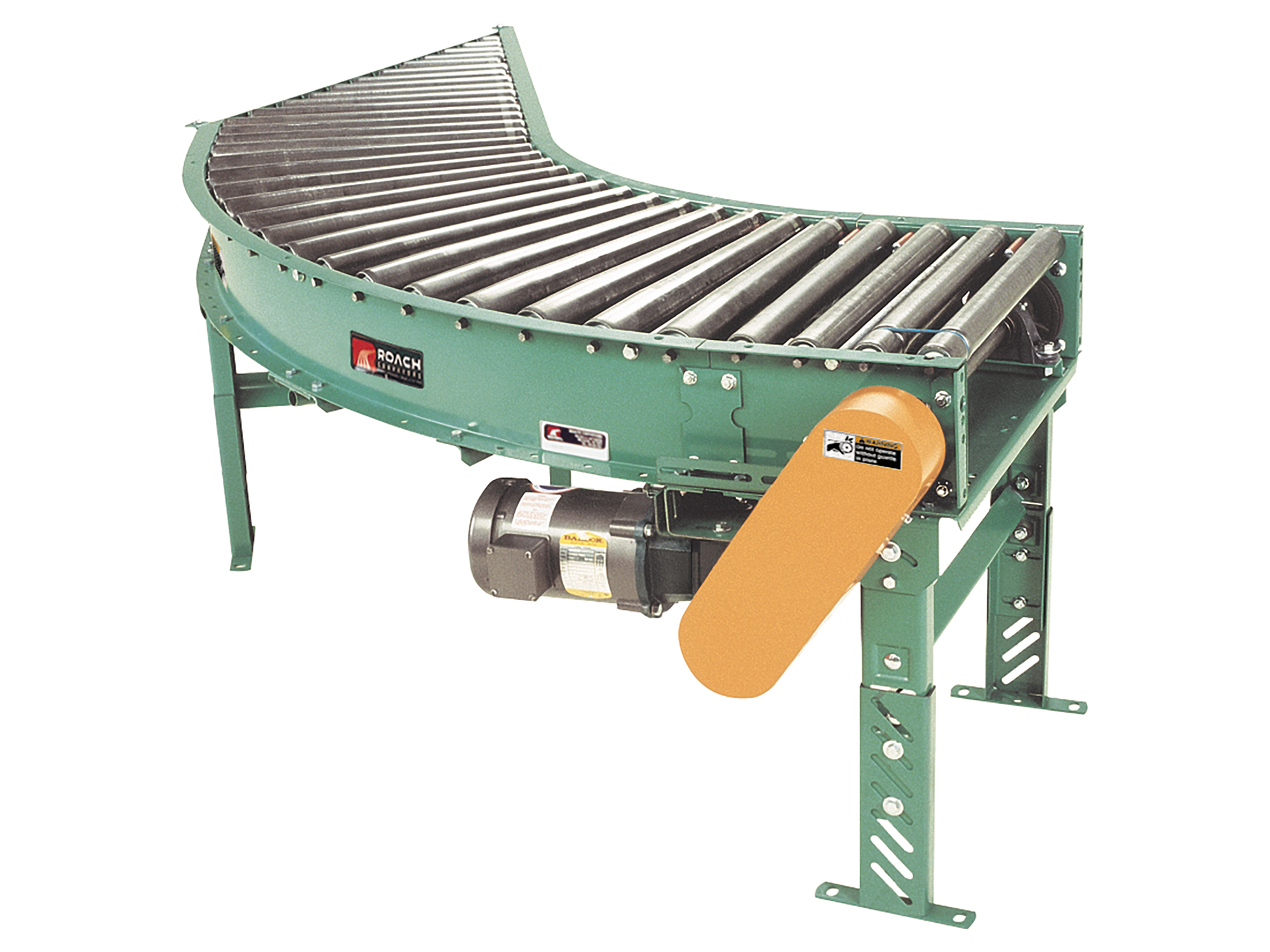
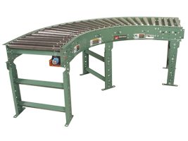
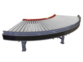
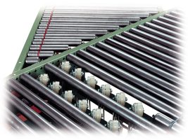
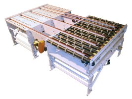
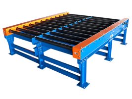
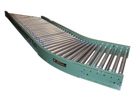
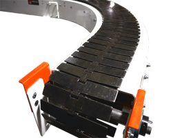
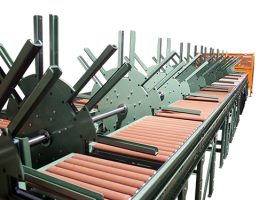
Model 196LRC features tapered rollers to maintain product orientation. Reversible, it is also commonly slave driven from 196VP and 796CALR conveyors.
196LRCS | Live Roller Medium Duty Spur Conveyor Curve
| Specifications | TREAD ROLLERS: 2-1/2″ dia. to 1-11/16″ dia. x 14 ga. steel tapered rollers, model 254T; 1.9″ dia. x 16 ga. steel straight tangent rollers, model 196S. PRESSURE SHEAVES: Provides drive belt pressure to upper tread rollers. BELTING: “B” section V-belt. TAKE-UP: Screw type adjustable sheave with flat idler sheaves to maintain belt tension. TANGENTS: 12″ opposite spur end on 60/30 unit; 18″ opposite spur end on 45/45 unit. SPEED: 60 FPM, constant. BED: 7″ x 1-1/2″ x 12 ga. formed steel channel frame. BEARINGS: End shafts are supported by precision, heavy duty, lubricated, ball bearing units with cast iron housings. ROLLER CHAIN: Drive shaft is driven by No. 50 chain. FLOOR SUPPORTS: Optional DRIVE LOCATION: Drive located on outside of curve. Specify left hand tangent length, right hand tangent length and drive location (“left hand drive” or “right hand drive”). NOTE: Drive hand determined with reference point located at outside of curve. For models slave driven (less drive), specify drive shaft location. CAPACITY: 500 lb. total distributed live load. MOTOR DRIVE: 1/3 HP, 230/460/3, 60 cycle, ODP right angle gear motor, located at infeed end of curve below bed. ELECTRICAL CONTROLS: Optional |
|---|
196LRCS
Model 196LRC features tapered rollers to maintain product orientation. Reversible, it is also commonly slave driven from 196VP and 796CALR conveyors.
| Specifications | TREAD ROLLERS: 2-1/2″ dia. to 1-11/16″ dia. x 14 ga. steel tapered rollers, model 254T; 1.9″ dia. x 16 ga. steel straight tangent rollers, model 196S. PRESSURE SHEAVES: Provides drive belt pressure to upper tread rollers. BELTING: “B” section V-belt. TAKE-UP: Screw type adjustable sheave with flat idler sheaves to maintain belt tension. TANGENTS: 12″ opposite spur end on 60/30 unit; 18″ opposite spur end on 45/45 unit. SPEED: 60 FPM, constant. BED: 7″ x 1-1/2″ x 12 ga. formed steel channel frame. BEARINGS: End shafts are supported by precision, heavy duty, lubricated, ball bearing units with cast iron housings. ROLLER CHAIN: Drive shaft is driven by No. 50 chain. FLOOR SUPPORTS: Optional DRIVE LOCATION: Drive located on outside of curve. Specify left hand tangent length, right hand tangent length and drive location (“left hand drive” or “right hand drive”). NOTE: Drive hand determined with reference point located at outside of curve. For models slave driven (less drive), specify drive shaft location. CAPACITY: 500 lb. total distributed live load. MOTOR DRIVE: 1/3 HP, 230/460/3, 60 cycle, ODP right angle gear motor, located at infeed end of curve below bed. ELECTRICAL CONTROLS: Optional |
|---|
196LRCS
Accumulation Conveyors(9)
Accumulation
Belt Conveyors(10)
Belt Conveyors
Belt Driven Live Roller(7)
Belt Driven Live Roller
Chain Drag(5)
Chain Driven Live Roller(11)
Chain Driven Live Roller
Flexible Conveyors(2)
Flexible Conveyors
Gravity Conveyors(19)
Gravity Conveyors
Line Shaft(9)
Line Shaft
MDZ | Motor Driven Zone Accumulator(2)
MDZ | Motor Driven Zone Accumulator
Parts Conveyor(3)
Parts Conveyor
Plastic Belt(9)
Plastic Belt
Powered Roller(13)
Powered Roller
Singulation(1)
Singulation
Slat Conveyors(2)
Slat Conveyors
Transfers(8)
Transfers
Wire Mesh Belt(4)
Wire Mesh Belt
Barrel Conveyors(3)
Barrel Conveyors
Glass & Solar Handling(8)
Glass & Solar Handling
Heavy Duty Conveyors(16)
Heavy Duty Conveyors
Laundry(11)
laundry
Lumber & Door(5)
Lumber
MDR | Motor Driven Roller Smart Conveyors(6)
MDR | Motor Driven Roller Smart Conveyors
Sortation Conveyors(7)
Sortation Conveyors
Special Transfers(11)
Special Transfers
Stackers | Destackers(2)
Stackers/Destackers
Stops | Barriers | Walkovers(10)
Stops | Barriers | Walkovers
Tabletop Chain Conveyors(5)
Tabletop Chain Conveyors
Transfer Carts(9)
Transfer Carts
Turntables(17)
Turntables
Upenders | Downenders | Rollovers(10)
Upenders | Downenders | Rollovers
Vertical Conveyors(8)
Vertical Conveyors
Wheel & Tire Conveyors(4)
Wheel & Tire Conveyors

